Valve symbols are used in process and instrumentation diagrams (P&ID), which are important in manufacturing industries such as oil and gas, HVAC, chemical, and food processing industries. These symbols ensure that every known valve type, its working, and its relation with other systems can be represented in a common standard.
For those working in engineering or process design for valves, it is important to comprehend valve symbols for the purpose of creating effective systems for operations.
In this article, you will learn the following aspects about the valve symbols: The commonly used symbols include the gate valve symbol, ball valve symbol, control valve symbols, and hydraulic valve symbols. You will also be able to read symbols of valves, understand their meaning on the P&ID diagrams, and understand their uses in different fields.
And once you’ve reached the end of the guide, you will be equipped with valuable knowledge sufficient enough to interpret valve symbols together with instances of their use.
What Are Valve Symbols, and Why Are They Important?
What Are Valve Symbols?
Valve symbols are graphical representations of valves that are used in engineering drawings, especially P&ID diagrams. It aids in the representation of liquid or gaseous fluids in a particular system and gives a perspective of how the different valves should connect with pumps, loaders, and tanks. These symbols guarantee that, from engineers to technicians and even vendors, everyone uses the same language when designing, operating, or even troubleshooting a system.
Why Are Valve Symbols Important?
If you have been a professional in the engineering field and at one point you stared at a P&ID and did not know what to do, you are not alone. It may look like early learning valve symbols; however, when one gets some grip on the basics of learning valve symbols, then it will become much easier to manage through them.
Why should you care about valve symbols?
Improve system design: The symbols allow the systems to be designed easily according to the required flow rate, pressure, and temperature range.
Increase control: For illustration, based on this symbol, it is possible to determine risks such as overpressure or backflow of fluids.
Optimize maintenance: As a next step, knowing the type of valve and its application makes it possible to solve problems efficiently.
Common Valve Symbols and Their Meanings
Gate Valve Symbol
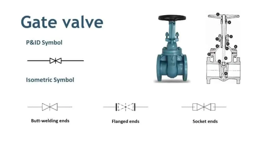
The gate valve symbol is one of the most common symbols in the P&ID diagrams, as it is one of the simplest types of valves. It is an emblem of two triangles facing each other, forming an arrow-like structure with an intended straight-through signal flow. Gate valves are mainly applied for on-off purposes, which means they only allow or prevent the flow of media through the line but do not regulate it.
Advantages of Gate Valves:
- Minimal pressure drop.
- The full bore design is expected to give an unhampered flow free from any obstruction.
Related Resource: Learn about gate valve applications and designs in RUFSUPPLY’s Gate Valve Guide.
Ball Valve Symbol
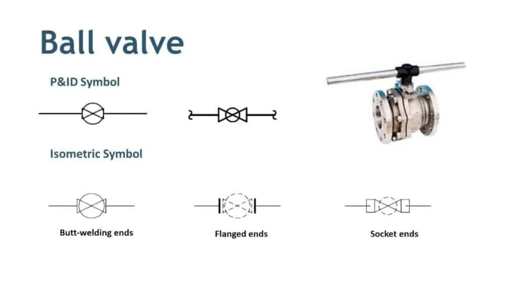
The ball valve symbol represents a valve with a rotary ball and a bore that controls the flow of liquid or gas. In P&ID diagrams, this symbol usually looks like a circle with a smaller filled-in circle in the center. Ball valves are known for their durability and ability to handle high pressures and temperatures.
Typical Applications of Ball Valves:
- HVAC systems.
- Oil and gas pipelines.
- Water distribution networks.
Ready to dive deeper? Check out our Complete Guide to Ball Valves.
Control Valve Symbol

A control valve symbol in a P&ID diagram represents a valve that regulates flow, pressure, or temperature in a system. These symbols often include an actuator symbol to indicate automation, such as pneumatic or electric control.
Key Uses of Control Valves:
- Maintaining process stability in chemical plants.
- Precise flow control in HVAC systems.
- Pressure regulation in pipelines.
Control valves play a critical role in ensuring your system operates efficiently and safely.
More Information: Explore control valve designs in RUFSUPPLY’s Control Valve Resources.
Real-World Industry Case Studies
Case 1: HVAC Systems and Control Valves
In large-scale HVAC (heating, ventilation, and air conditioning) systems, control valves are critical for regulating temperature and airflow.
- Application Example: In a commercial building, control valves are used to adjust the flow of chilled water to air handling units (AHUs). By modulating the valve positions, the system can maintain a constant room temperature.
- Symbol Explanation: In a P&ID, the control valve is often depicted with an actuator symbol above it, indicating that it is controlled by an electric or pneumatic signal.
- Practical Impact: Proper use of control valves ensures energy efficiency, reduces operational costs, and improves occupant comfort.
Case 2: Safety Valves in Oil and Gas Pipelines
Safety valves are vital in preventing overpressure incidents in oil and gas pipelines.
- Application Example: In a high-pressure pipeline, safety valves automatically release excess pressure to avoid equipment damage or catastrophic failure.
- Symbol Explanation: Safety valve symbols often include arrows to show the direction of flow relief.
- Practical Impact: By including safety valve symbols in P&ID diagrams, engineers ensure compliance with safety standards and protect both personnel and equipment.
Case 3: Diaphragm Valves in Food and Beverage Processing
Sanitary design and examination of the diaphragm valves make it popular in the food and beverages industries, particularly when handling sensitive fluids.
Application Example: At the dairy processing company, diaphragm valves are used in controlling the flow of milk as well as other fluids to improve hygiene.
Symbol Description: The symbol of the diaphragm valve generally has a straight line with a curved line on top of it that looks like the flexible diaphragm in the valve.
Real-life Application: They help avoid deterioration of the food products by preventing the flow of impure substances and meet the required hygiene standards.
Explore More: Learn about food-safe valve designs in RUFsupply’s Valve Applications.
How to Read Valve Symbols on Drawings
Understanding valve symbols on drawings is about more than just recognizing the shapes. You also need to interpret their context within the diagram, including flow direction, actuation type, and connection style.
Conclusion and Reader Engagement
Valve symbols are the graphic representations of the actual valve used to describe and demonstrate procedure to design, to keep and to analyze the complexes of process and instrumentation diagrams. Indeed, this area depends on whether you are using a gate valve symbol or any other type of symbol such as a control valve symbol or hydraulic valve symbol, doing so will diversify your knowledge and also help you become more efficient in your work.